How to Use the USGS Interactive Map Interface
The purpose of this guide is to assist in the use of the user interface that is provided with
the interactive maps of the USGS
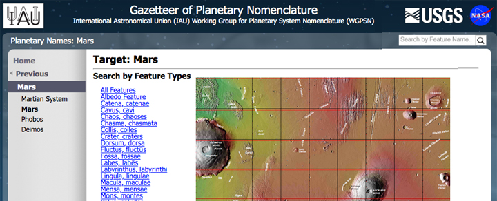
Gazetteer site. This interface appears when viewing a record of one of the USGS
Gazetteer links from the "Maps" menu of this site or by clicking on the
![]() icons found in the Index lists.
icons found in the Index lists.
Table of Contents
Map Guide to the Gazetteer
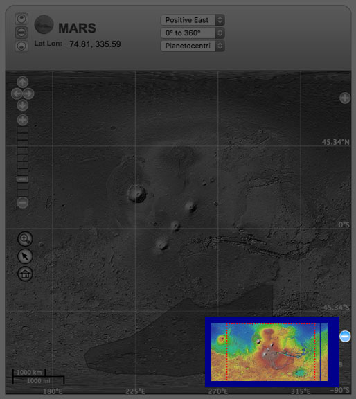
Here is what a typical map looks like:
The various elements of the map interface will be explained in detail below.

Top Console

The top console of the map interface lets you choose how you want to navigate the planetary map. It includes the following items:
Map Projections

Current Target

Current Lat/Lon Position

Latitude/Longitude Specifications

Planetographic coordinates or planetocentric coordinates?
Two systems are currently in use, although the second one tends to be generalized - both within NASA and ESA - at the
expense of the first one:
- Latitudes were initially determined in a planetographic framework consisting in calculating them directly from distances extrapolated on the obtained images of the planet surface with respect to a grid of coordinates projected on this surface. In this system, used by the Viking program, the longitudes are expressed from 0 to 360° W, that is to say in increasing towards the west.
- Since the beginning of the century, the planetographic system tends to be replaced by the planetocentric system, although both were validated by the IAU in 2000. In this system, latitudes are calculated from the angle formed by a point on the surface with the equatorial plane of Mars, while longitudes are expressed from 0 to 360° E, i.e. increasing towards the east.
Navigating the Map
There are several tools available that allow the navigation of a map:
Panning

Zooming


Middle: navigate by clicking and dragging.
Bottom: Refocus on the selected object.
Navigation using the inset map
You can also navigate the map by clicking and dragging a box that is overlayed on an inset map. Click the plus (+) button
at the bottom right of the map, and a small menu will appear, displaying the inset map. You can click and drag the rectangle
to different parts of the map to pan to that location. Click on the minus (-) button to close the menu.
Choosing Different Map Layers and Overlays
You can choose to display a different base layer and overlay(s) for the map by clicking on the plus (+) button at the top right of the map. A menu will be displayed that will allow you these choices. Each part of the menu is described in more detail below.

Choosing Different Overlays

Overlays:
Graticule (Lat/Lon grid)
Feature Boundaries
Mars 500K Quad Charts
Mars 2M Quad Charts
Mars 5M Quad Charts
Show Feature Names
Show Feature Names : when this checkbox is checked, features will be displayed on the map. Keep in mind, the further zoomed out you are the more features you will see which can take longer to load.
Here is an example of what the map looks like when the 'Nomenclature Features' option is selected.
Choosing Different Base Layers
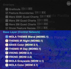
Base layers:
MOLA THEMIS Blend (MDIM 2.1)
THEMIS IR Night (MDIM 2.1)
AMES Color (MDIM 2.1)
THEMIS IR Day (MDIM 2.1)
VIKING (MDIM 2.1)
VIKING (MDIM 2.0)
MOLA Grayscale (MDIM 2.1)
MOLA Color (MDIM 2.1)
The MDIM (Mars Digital Image Model) version 2.1 image mosaic replaces two
previous mosaics produced by the USGS from the same set of about 4600 Viking Orbiter images. The positional accuracy of features
in MDIM 2.1 is estimated to be about one pixel (200 m), compared to 3 km for MDIM 2.0 released in 2001
and more than 6 km for MDIM 1.0 released in 1991.
Mars Global Surveyor MGS, orbiter which studied the atmosphere and the surface of Mars from 1997 to 2006 was to answer the many questions raised by the data collected under the Viking program launched 20 years before. This probe carried, among other things, the MOC (Mars Orbiter Camera) camera with a powerful telephoto lens designed to obtain detailed images of the geological structures of the surface with an effective spatial resolution between 2.5 and 3 meters and a MOLA (Mars Orbiter Laser Altimeter) laser altimeter that measures the altitude of the surface of Mars. The final objective is to produce a high-resolution topographic map with a vertical accuracy of at least 30 meters, more focused maps with a vertical accuracy of 2 meters and to provide a global map of the reflectivity of the surface of Mars.
The Thermal Emission Imaging System
THEMIS spectrometer of the 2001_Mars_Odyssey probe, launched on April 7, 2001 and placed in orbit around Mars on October 24, 2002, has mapped
the geological resources of Mars via a high-definition camera coupled to a spectrometer working in infrared and visible light.
The Gamma Ray Spectrometer GRS was also used to determine the elements composing the surface of Mars.
2001 Mars Odyssey, whose mission has been extended 5 times, is still operational in 2020, more than nineteen years after its launch.
The Ames Research Center (AMES) is involved in virtually every space exploration probe project as a designer or subcontractor for equipment or testing. AMES also works on the space program to search for life in the universe, the development of life support systems for future missions, and the effects of space on humans.
The Viking program launched two identical space probes, Viking 1 and Viking 2. Each of these missions consisted of a spacecraft designed to orbit the planet and a module that would land on the ground and conduct investigations on site without the means of travel. It was this program that landed the first American spacecraft on Mars. The scientific objectives were to make high-resolution images of the planet's surface, to determine the structure and composition of the atmosphere and to identify the possible presence of life on Mars.
Viking 1 orbiter arrived on June 19, 1976 and operated until November 13, 1982. The mission lasted 4 years, 1 month and 19 days. Its lander Viking 1 Lander had a longer life, landed on July 20, 1976, it stopped working after 6 years, 3 months and 22 days.
Viking 2 orbiter, arrived on August 7, 1976, worked until July 25, 1978 (life duration of 1 year, 11 months and 18 days). Viking 2 Lander had a longer life, landed on September 3, 1976, it stopped working after 3 years, 7 months and 8 days because of the failure of its battery.
Based on Astrodocs.wr.usgs.gov - Nomenclature: How_to_Use_the_Map_Interface
Documentary sources, articles, databases:
Wikipedia |
USGS |
IAU |
Nasa |
MSSS
All the documents presented here are linked to their owners on their respective official site. ©Ifik |
Contact